2016-04-07
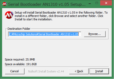
アプリケーションノートのインストール。たぶんプログラムを解凍して配置しているだけ
USBブートローダーはこちらの記事を参照
ブートローダーを使用した回路の例(ネオン管時計)
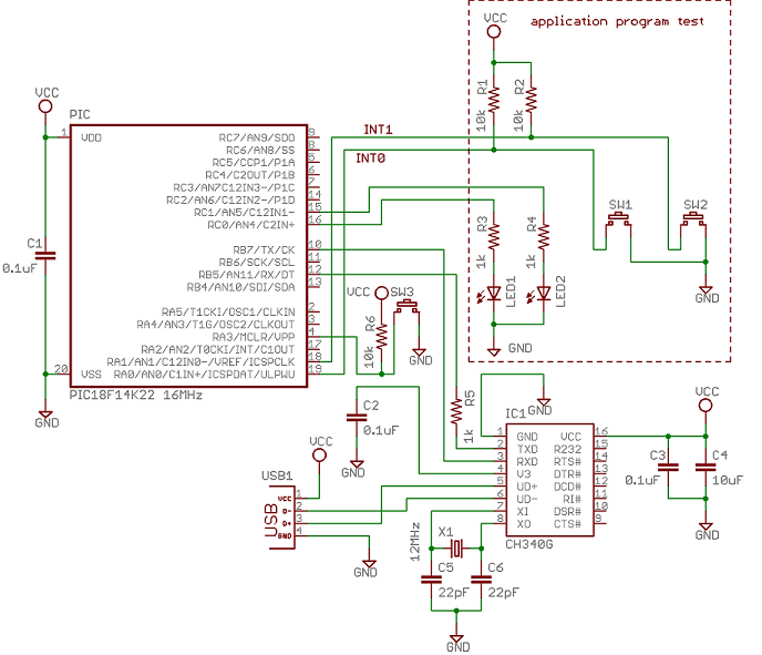
動作確認用の回路図。点線内はアプリケーションファームウェアの動作確認用のハード。USBシリアル変換ICにCH340Gを使用しているがFT232でも動く。CH340GはAliexpressで購入できる。PICは内部発振機能を使っているのでOSC1,OSC2に水晶が繋がっていない。R5は不要
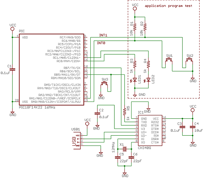
MCLRピンをアプリケーションファームウェアで入力ピンとして使用している場合はこうする。SW3を押しながら電源を入れるとブートローダーファームウェアが起動。SW3を押さずに電源を入れればアプリケーションファームウェアが起動
ブートローダーファームウェアのconfigurationワードはアプリケーションファームウェアと同じにする
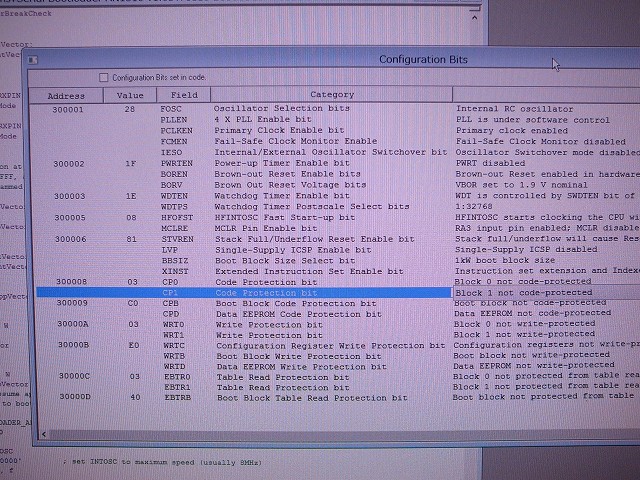
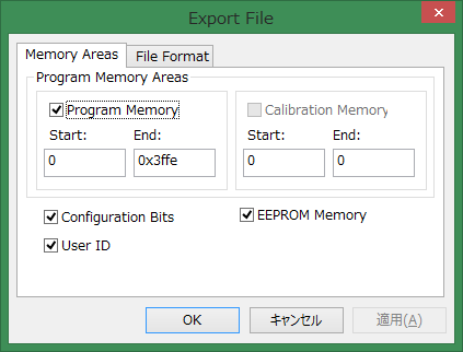
ブートローダーファームウェアをMPLAB以外のソフトを使って書き込むときはEXPORTしないとconfigurationワードがHEXファイルに含まれないので注意
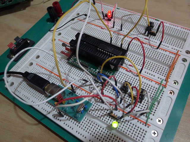
上の回路の実際。CH340Gは緑色の基板の裏側にある
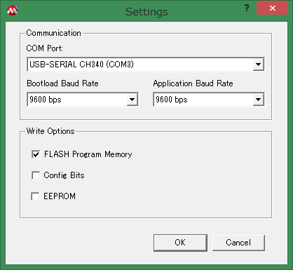
ブートローダープログラムの設定。ボーレートは大きいほど書き込みが速くなる。Application Baud Rate はアプリケーションファームウェアの書き込みには無関係。AN1310のサンプルアプリケーションファームウェアの動作確認のための物。自作したアプリケーションファームウェアなら無関無い
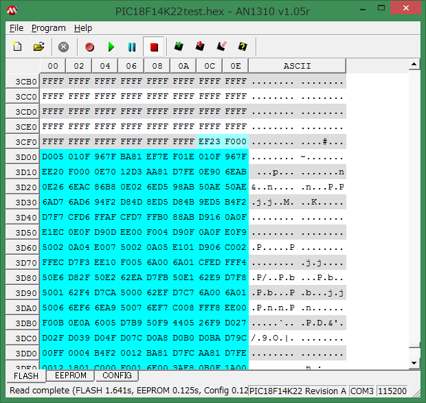
ブートローダープログラムの画面
赤■:ブートローダーファームウェアと通信を開始。ブートローダーファームウェアが起動している必要がある
水色||:RXピンを0Vにする。上の回路図においてはブートローダープログラムによってCH340GのTXDピンが0Vになる
赤色↓:アプリケーションファームウェアの書き込み
右上の水色の値はアプリケーションファームウェアが書き込まれていないときはFFFFになっていることもある。ここはブートローダーファームウェア先頭アドレスへのJUMP命令
豆知識)FFFFを命令として実行すると何もせずに次のアドレスの命令が実行される。全てのメモリーがFFFFで埋められていると何も起こらない
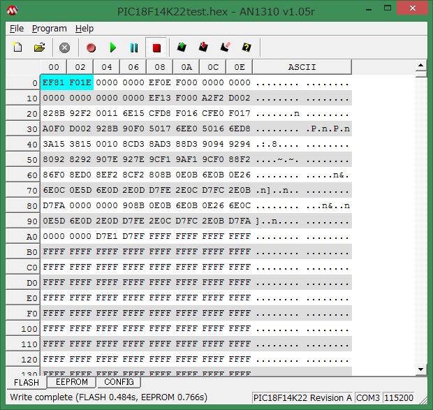
水色部分がブートローダーファームウェア。どんなコードなのか確認したいときはMPLAB IDEでHEXファイルを[File]-[Import...]して[View]-[Program Memory]で表示すると逆アセンブルされる
0001  '===============================================================================
0002  ' bootloader sample application program
0003  '===============================================================================
0004  program PIC18F14K22test
0005
0006  symbol LED1_TRIS  = TRISC0_bit
0007  symbol LED1       = LATC0_bit
0008  symbol LED2_TRIS  = TRISC1_bit
0009  symbol LED2       = LATC1_bit
0010
0011  symbol SW1_TRIS  = TRISA0_bit
0012  symbol SW1_PORT  = RA0_bit
0013  symbol SW2_TRIS  = TRISA1_bit
0014  symbol SW2_PORT  = RA1_bit
0015
0016
0017  '===============================================================================
0018  ' Interrupt
0019  '===============================================================================
0020  sub procedure interrupt  ' high priority interrupts
0021    if INT0IF_bit = 1 then
0022      LED2 = 1  ' LED2 ON
0023      INT0IF_bit = 0
0024    end if
0025  end sub
0026
0027  sub procedure interrupt_low  ' low priority interrupts
0028    if INT1IF_bit = 1 then
0029      LED2 = 0  ' LED2 OFF
0030      INT1IF_bit = 0
0031    end if
0032  end sub
0033
0034  '===============================================================================
0035  ' main
0036  '===============================================================================
0037  main:
0038    IRCF2_bit = 1   ' internal osc 16MHz
0039    IRCF1_bit = 1
0040    IRCF0_bit = 1
0041
0042    LED1_TRIS = 0 ' PORT OUTPUT
0043    LED2_TRIS = 0 ' PORT OUTPUT
0044    SW1_TRIS  = 1 ' PORT INPUT
0045    SW2_TRIS  = 1 ' PORT INPUT
0046    ANS0_bit  = 0 ' SW1 digital input
0047    ANS1_bit  = 0 ' SW2 digital input
0048
0049    INTEDG0_bit = 0 ' Interrupt on falling edge
0050    INTEDG1_bit = 0 ' Interrupt on falling edge
0051    INT1IP_bit  = 0 ' INT1 Low  priority interrupt
0052    INT0IE_bit  = 1 ' Enable INT0 interrupt
0053    INT1IE_bit  = 1 ' Enable INT1 interrupt
0054
0055    IPEN_bit    = 1 ' Enable priority levels on interrupts
0056    GIEH_bit    = 1 ' Enables all high priority interrupts
0057    GIEL_bit    = 1 ' Enables all low  priority interrupts
0058
0059    while true     ' blink LED1
0060      LED1 = 1
0061      delay_ms(500)
0062      LED1 = 0
0063      delay_ms(500)
0064    wend
0065  end.