2014-12-22
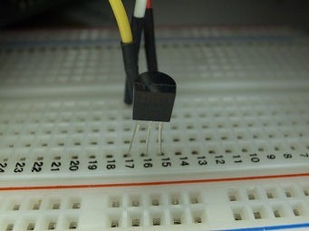
普通のトランジスターパッケージTO-92形。ライブラリーの基本構造はMAXIMが公開しているのでこれを各言語に移植すれば良い。arduinoのライブラリーはここ1本の通信線に複数のデバイスを接続できる規格のため各デバイスを認識するためのサーチアルゴリズムがちょっと複雑。正面左から GND 信号 VDD のピン配列

2020-11-20
センサーは防水タイプ

PIC24FJ64GA002 xc16コンパイラでの実例
0001  //------------------------------------------------------------------------------
0002  // File:   ondokei_DS18B20.c
0003  // Created on 2020/11/19, 9:23
0004  //------------------------------------------------------------------------------
0005  #define p24FJ64GA002
0006
0007  #define FOSC 32000000
0008  #define FCY  (FOSC/2)
0009
0010  #define USE_AND_OR
0011
0012  #include <xc.h>
0013  #include <stdio.h>
0014  #include <stdbool.h>
0015  #include <libpic30.h>
0016  #include <uart.h>
0017  #include <PPS.h>
0018
0019  #pragma config POSCMOD  = HS
0020  #pragma config FNOSC    = PRIPLL
0021  #pragma config OSCIOFNC = OFF
0022  #pragma config FWDTEN   = OFF
0023  #pragma config FCKSM    = CSDCMD
0024
0025  #define BAUD_RATE    9600
0026  #define UxBRG_ARG  (((FCY/BAUD_RATE)/16)-1)   // = 103
0027
0028  #define PORT_INPUT  1
0029  #define PORT_OUTPUT 0
0030
0031  #define OW_HIGH  1
0032  #define OW_LOW   0
0033
0034  #define OW_SET    1
0035  #define OW_CLEAR  0
0036
0037  #define OW_LAT   LATBbits.LATB3
0038  #define OW_PORT  PORTBbits.RB3
0039  #define OW_TRIS  TRISBbits.TRISB3
0040
0041  #define DS18B20_RESET_ERROR 0x0800
0042
0043  void drive_OW_high(void)
0044  {
0045    OW_TRIS = PORT_OUTPUT;
0046    OW_LAT  = OW_HIGH;
0047  }
0048
0049  void drive_OW_low(void)
0050  {
0051    OW_TRIS = PORT_OUTPUT;
0052    OW_LAT  = OW_LOW;
0053  }
0054
0055  void drive_OW_input(void)
0056  {
0057    OW_TRIS = PORT_INPUT;
0058  }
0059
0060  unsigned char read_OW(void)
0061  {
0062    unsigned char read_data;
0063
0064    OW_TRIS = PORT_INPUT;
0065
0066    if(OW_PORT == OW_HIGH) {
0067       read_data = OW_SET;
0068    } else {
0069      read_data = OW_CLEAR;
0070    }
0071
0072    return read_data;
0073  }
0074
0075  //------------------------------------------------------------------------------
0076  //  return 0:connection error 1:sensor is present
0077  //------------------------------------------------------------------------------
0078  bool OW_Reset(void) {
0079    unsigned char presence_detect;
0080
0081    drive_OW_low();
0082    __delay_us(480);
0083    drive_OW_input();
0084    __delay_us(480);
0085    presence_detect = read_OW();
0086    __delay_us(410);
0087
0088    return presence_detect;
0089  }
0090
0091  void OW_write_bit (unsigned char write_bit)
0092  {
0093    if( write_bit ){    //writing a bit '1'
0094      drive_OW_low();       // Drive the bus low
0095      __delay_us(6);        // delay 6 microsecond (us)
0096      drive_OW_high();       // Release the bus
0097      __delay_us(64);        // delay 64 microsecond (us)
0098    }  else {           //writing a bit '0'
0099      drive_OW_low();         // Drive the bus low
0100      __delay_us(60);          // delay 60 microsecond (us)
0101      drive_OW_high();        // Release the bus
0102      __delay_us(10);          // delay 10 microsecond for recovery (us)
0103    }
0104  }
0105
0106  unsigned char OW_read_bit (void)
0107  {
0108    unsigned char read_data;
0109    //reading a bit
0110    drive_OW_low();        // Drive the bus low
0111    __delay_us(6)           // delay 6 microsecond (us)
0112    drive_OW_high();       // Release the bus
0113    __delay_us(9)           // delay 9 microsecond (us)
0114
0115    read_data = read_OW(); //Read the status of OW_PIN
0116
0117    __delay_us(55);         // delay 55 microsecond (us)
0118    return read_data;
0119  }
0120
0121  void OW_write_byte(unsigned char write_data)
0122  {
0123    unsigned char loop;
0124
0125    for( loop = 0 ; loop < 8 ; loop++ )  {
0126      OW_write_bit(write_data & 0x01);   //Sending LS-bit first
0127      write_data >>= 1;                 // shift the data byte for the next bit to send
0128    }
0129  }
0130
0131  unsigned char OW_read_byte (void)
0132  {
0133    unsigned char result = 0;
0134    unsigned char loop;
0135
0136    for( loop = 0 ; loop < 8 ; loop++ ) {
0137      result >>= 1;         // shift the result to get it ready for the next bit to receive
0138      if( OW_read_bit() ) {
0139        result |= 0x80;        // if result is one, then set MS-bit
0140      }
0141    }
0142    return result;
0143  }
0144
0145  int ds18b20_read(void)
0146  {
0147    uint16_t raw_temp_value;
0148
0149    if(OW_Reset() == 0) {   // send start pulse
0150      return DS18B20_RESET_ERROR;
0151    }
0152
0153    OW_write_byte(0xCC);   // send skip ROM command
0154    OW_write_byte(0x44);   // send start conversion command
0155
0156    while(OW_read_byte() == 0) { ; }  // wait for conversion complete
0157
0158    if(OW_Reset() == 0) {   // send start pulse
0159      return DS18B20_RESET_ERROR;
0160    }
0161
0162    OW_write_byte(0xCC);  // send skip ROM command
0163    OW_write_byte(0xBE);  // send read command
0164
0165    raw_temp_value  = OW_read_byte();         // read temperature LSB byte and store it on raw_temp_value LSB byte
0166    raw_temp_value |= (OW_read_byte() << 8);  // read temperature MSB byte and store it on raw_temp_value MSB byte
0167
0168    return (int)raw_temp_value;
0169  }
0170
0171  int main(void) {
0172    int raw_tmperature;
0173    char buf[20];
0174
0175    iPPSOutput( OUT_PIN_PPS_RP13, OUT_FN_PPS_U1TX );
0176    iPPSInput(  IN_FN_PPS_U1RX,  IN_PIN_PPS_RP14  );
0177    OpenUART1( UART_EN, UART_TX_ENABLE, UxBRG_ARG );
0178
0179    AD1PCFGbits.PCFG5 = 1; // 1=digital mode
0180
0181    while( true ) {
0182      raw_tmperature = ds18b20_read();
0183      if( raw_tmperature == DS18B20_RESET_ERROR ) {
0184        sprintf(buf, "reset error\n" );
0185      } else {
0186        sprintf(buf, "%10.4f\n",  (double)raw_tmperature * 0.0625);
0187      }
0188      putsUART1( (unsigned int *)buf );
0189    }
0190  }
行番号
解説
153,154
シリアル通信、TX:RP13ピン RX:RP14ピン RXは使っていないがコードは書いてある。PIC24はPPSという機能で好きなポートにシリアル通信を割り当てられる
179
A/DポートチャネルだけはPPSではなく固定のポートに割り当てがある。PIC18シリーズなどではADCONという名前。これをやらないと入力ポートはデフォルトでアナログポートになるためPORTの状態を読みだしてもゼロが返ってくる
2021-06-25
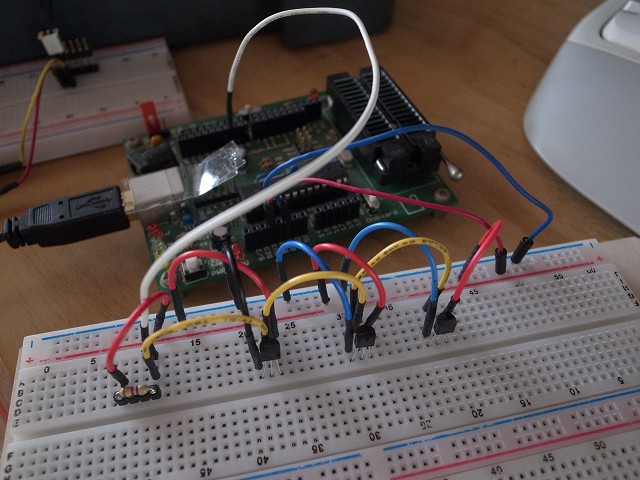
複数センサーの識別はセンサーに書き込まれているIDで行う。IDを読み出す必要があるので汎用ソフトを書けない。指でつまんで温度が上がったIDの物がそれだと確認できる。デイジーチェーンなら何番目につながっている物という方法で個体認識できるが1-wireはタコ足配線なので順番があるわけではない。IDを読みださないと個体識別が出来ないので1つのバスに複数の同一センサーを接続する使い方を想定していないと思われる
